|
|
|
|
Stop electromagnets controller - technical data
- voltage rating: 7 - 30V
- supply current without load: 50mA
- control voltages: 5/12/24V
- maximum turned on voltage: 30V
- maximum load current: 2x15A limited to 2x3A by fuses
- duration of impulses turning on electromagnets, digitally setup within the range of few dozen ms up to a few seconds (buttons for extending and shortening the time)
- reset button
- default adjustment button
- dimensions: 105 x 35 x 24mm (the given height takes into account elements on the bottom side of the board)
- parts height above the board: 20mm
|
 |
|
 |
|
Specification
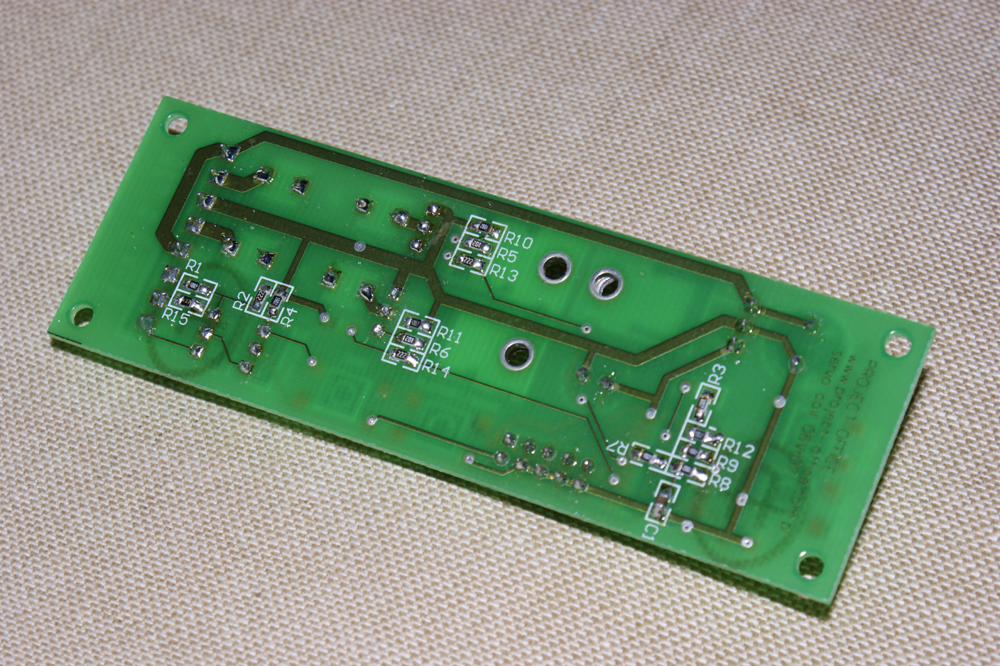
The stop electromagnet controller temporarily turns on voltage for coils which move the rod connected with the slider. In this way, the organ stops can be turned on/off. Two PowerMOSFET transistors have been used as active components. Their maximum current load is 15A, but it is limited to 3A by fuses. As these transistors work without radiators, exchanging the fuses for fuses of higher current can lead to overheating of transistors. Transistors gates are driven by the processor applied. We apply the processor in order to entirely eliminate the influence of time on RC elements used in traditional solutions. The set up time of turning on the voltage is always the same. We can adjust the time to the slider mechanics with the use of two buttons: one for lengthening and another for shortening. Pressing the buttons lengthens or shortens the time by a default value and is also indicated by a single flash of the LED. The time can be changed within a wide range (from a few dozen ms up to a few seconds or otherwise according to the order). The time can be changed until the LED flashes twice. These two flashes inform about reaching the upper or the lower limit. The time programmed by the producer can be restored by holding pressed the "reset/default" button until the LED flashes. This button has two functions. Pressing it for a short time restores output levels to those which occurred after turning on the controller. When we press the button for a few seconds (until the LED flashes), we restore the default time that was programmed by the producer.
The controller has another button which can be used to test the set time. We can press this button to activate the same action as in the course of regular work. It allows the person who installs the controller in an organ to set up the time precisely and freely, in place where the controller and the electromagnets are installed.
The device has two switches: "test - normal work" and control by the setzer (5V) - control with other voltages. The controller has also three inputs for: 24V, 12V and 5V (you can use only one input at a time). The high level or the low level is active (according to the order). The controller starts working after about 2 seconds from turning on the supply voltage which is indicated by a single LED flash.
All coil terminals should be connected to the controller. The terminals of overvoltage dumping elements (if not installed in coils) must be inserted in a proper way into the same slots where coil terminals are connected. Turning on the coil voltages are indicated by flashing LEDs. The standard controller work can be changed according to the order.
| |
|
|
|
|
|