Specification
Organ stops are turned on/off manually or by stop knob controllers. The knob is moved by electromagnets connected to the controller. Admitting voltage to an input pulls out the knob. Our controller is designed for knob units which do not have devices that turn off the supply current when knobs were pulled out. These knob units have relays which admit voltage to electromagnets, moving organ stop sliders. The controller is adapted to work with the setzer. When knob is pulled out manually or by the setzer, the controller admits voltage to the electromagnet which pulls out the knob (even if the knob was pulled out manually). At the same time, the controller tests the second input voltage. This input should be connected to voltage from the above mentioned relay. When the second input voltage level is high, the controller turns off the current supply to the electromagnet pulling out knob. In the same way knob is slipped when the first input voltage is turned off by the setzer or when the knob is pushed manually.
The controller also has an output through which it informs the setzer about pulling/pushing the knob. This output should be connected to the setzer input but not to any other input. It must be the same input which turns on/off the stop that is turned on/off by the controller.
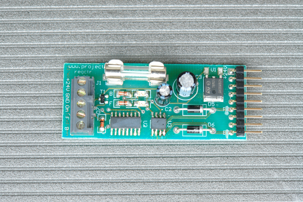
The controller has two fast diodes on the board which are used for dumping overvoltages. If there are any overvoltage dumping diodes inside the knob unit, they must be removed. It is caused by the transistors which have been used to supply voltage to the electromagnets by the controller. The controller contains PowerMOSFET relays. Therefore, you cannot connect knob electromagnets freely. Their common terminal should be connected to the positive terminal of the organ power supply and the terminals of the remaining two electromagnets should be connected to the controller. When the controller turns on these electromagnets, these two terminals are short-circuited to the organ ground terminal depending on whether the knob is pulled or pushed. If the diodes used for overvoltage dumping in the knob unit are connected in the opposite direction to diodes used on the controller board, there will be a short-cut between the positive terminal with the ground terminal of the organ power supply through diodes used in the knob unit!
|
| |